


XeVision® integrated HID product specifications and features
Quick links specification list:
* Our digital ballasts are designed based on planar transformer technology and digital input power control.
* Built to RTCA/DO-160E standards with select ballast certified to RTCA/DO-160E
* Aluminum case with Silicon seal or Silicon O-ring, fully dust & waterproof designed to IP 67.
* Very low EMI/RFI due to digital design and superior shielding. Meets or exceeds RTCA/DO-160E standards.
* Uses resonant zero voltage switching technology, and our CR technology (Continuous Restrike technology).
* VPM: Variable Power Mode for dual power ballast models, also referred as DPM Dual Power Mode.
* SPM: Single Power Mode for single power wattage ballast models.
- Hot restrike with 75% output in less than 3 s
- Hot restrike based on our CR technology
- Output capable of driving up to 5 m shielded cable or D1 system
- High efficiency under wide range of operating conditions > 90%
- Drives D1S bulbs as well as D2S bulbs with our external ignitor
- 35, 50 and 75 watts systems (75 W special installation approval)
- VPM (DPM) capable (XV4D and XV8C)
- No flickering
- Active reverse input polarity protection
- Open and short output protection, response time < 0.5 s
- Input over-voltage protection; switches off with automatic restart
- Input under-voltage shut down, self locked
- Fast restart cycles
- Smooth lamp current curve
- Smart warm up control
- Long life (> 3000 hours)
XV4D
- Super thin, lightweight ballast
- With and without mounting tabs
- Drives D1S bulb as well as D2S bulb with our external ignitor or our XeSparQ D2/D1 adapter.
- with RTCA/DO-160E certification
XV4D 35 W, with or without mounting tabs

XV4D 50 W, with mounting tabs
XV4D 50 W, without mounting tabs

XV4D 75 W, with SS mounting bracket
Parameter
XV4D-35
XV4D-50
XV4D-75
Normal input voltage range (VDC)
8.5-18.5 / 18-32
8.5-18.5 / 18-32
8.5-18.5 / 18-32
Ext. input voltage range (VDC)
6 - 18 / 16 - 34
6 - 18 / 16 - 34
6 - 18 / 16 - 34
Starting input voltage range (VDC)
7 - 18 / 14 - 32
7 - 18 / 14 - 32
7 - 18 / 14 - 32
Nominal output power
35 W ± 2 W
50 W ± 2 W
75 W ± 2 W
Maximum run up output power
80 W (100 SAE)
100 W
112 W
Max. steady state lamp current
3.2 / 1.6 A
4.6 / 2.3 A
6.4 / 3.2 A
Max. inrush current at 13.5 / 27.0 VDC
6 / 3 A
8 / 4 A
10 / 5 A
Max. inrush current @ 10.0 / 20.0 VDC
8 / 4 A
10 / 5 A
12 / 6 A
Striking voltage
>1.3 KV
>1.3 KV
>1.3 KV
Steady state output volts (VAC)
60 to 110
60 to 110
60 to 110
Max. steady state input power (W)
41 / 40
58 / 55
90 / 85
Efficiency of D1S and ballast
>85 % / >88 %
>86 % / >91 %
>84 % / >88 %
Output steady state frequency
500 +/- 50 Hz
500 +/- 50 Hz
500 +/- 50 Hz
Temperature range
-40 to +105 °C
-40 to +105 °C
-40 to +105 °C
Water/dust environment
meets IP 67
meets IP 67
meets IP 67
EMI/RFI certification (with D1 bulbs)
meets RTCA/DO-160E
RTCA/DO-160E
RTCA/DO-160E
Weight (no wires, with tabs)
162 g
184 g
-
Weight (no wires, no tabs)
148 g
170 g
210 g
Stainless steel bracket
-
-
32 g
Black anodized Al heat sink (HS)
-
optional
included
Dimensions (tabs not included)
length: <84 mm width: <74 mm height: <15 mm
length: <84 mm width: <74 mm height: <23 mm
length: <84 mm width: <74 mm height: <32 mm
DPM available
no
yes
yes
*) CR Technology: Continuous Restrike technology
**) DPM: Dual Power Mode for ual power setting
VPM (DPM) explained:
Variable power mode means that two output power or dual power modes (DPM) settings can be variably selected (generally 50 watt and 35 watt for dimming purposes to conserve battery power or for two preset brightnesses. With our XePulse™ 2 DPM can be used to wig-wag by dimming instead of on-off.
XV6D - The Green Ballast
XeVision has finalized the first 35 watt D-series XeStrike™ ballast for driving Philips XenEcoStart™ Mercury-free (Hg-free) D3S and D4S HID bulbs. The D3S corresponds to the common D1S bulb with the same footprint, and so does the D4S with the standard D2S. Hg-free bulbs have very different and challenging electrical requirements for the ballast design. XeVision’s first production of the green slim-line ballast features an SAE type fast start-up bulb ignition. It is suitable for replacement of current HID systems, if ‘green’ compliance is necessary. This new ballast is intended for use in aviation (HID landing and taxi lights), military, and industrial applications.
OEM welcome.
Key features:
- digital XeStrike™ D-series XV8C ballast
- 35 watt
- 12 VDC or 24 VDC
- water and dust proof, to IP67
- Fast, SAE-type start-up

XV6D slim-line SAE ballast
Parameter
12 VDC - 35 W
24 VDC - 35 W
Normal op. input voltage range
8.5-18.5 VDC
18-36 VDC
Start-up (turn-off voltage) , VDC
8.5 (5.0) VDC
18 (12) VDC
Starting input voltage range, VDC
8.5-18.5 VDC
18-36 VDC
Nominal output power
35W ± 1 W
35W ± 1 W
Maximum run up output power SAE
100 W
100 W
Max. steady state lamp current
3.2 A
1.6 A
Max. inrush current at 13.5 / 27.0 VDC
6 A
3 A
Max. inrush current @ 10.0 / 20.0 VDC
8 A
4 A
Max. inrush current
20A at 50ms 7A at 2 s decreasing to Steady State within 45 sec
>10A at 50 ms 4.5A at 2 s decreasing to steady state within 45 sec
Striking voltage
>1.3 KV Pin 1 & Pin 4
>1.3 KV Pin 1 & Pin 4
Steady state output volts (VAC)
20 to 60 Vac
20 to 60 Vac
Efficiency system @ nom V
86 %
91 %
Steady state output voltage
60 to 110 VA
60 to 110 VAC
Turn On light output
>70% at 2 sec
> 80% at 3 sec.
>70% at 2 sec >80% at 3 sec.
Output steady state frequency
500 +/- 50 Hz
500 +/- 50 Hz
Temperature range
-40 to + 95 °C
-40 to + 95 °C
Temperature control (by custmer)
max. on case 75ºC
max. on case 75ºC
Weight (without bulb, heat sink)
184 g
184 g
Dimensions (without cables)
width: 30 mm
length: 115 mm
height: 20 mm
width: 30 mm
length: 115 mm
height: 20 mm
3 mounting holes for M5 bolts, distance
width: 45 mm
length: 98 mm
width: 45 mm
length: 98 mm
Radiated EMI emission $ susceptibility
DO-160E
DO-160E
Water/dust environment
IP 67
IP 67
DPM available
no
no
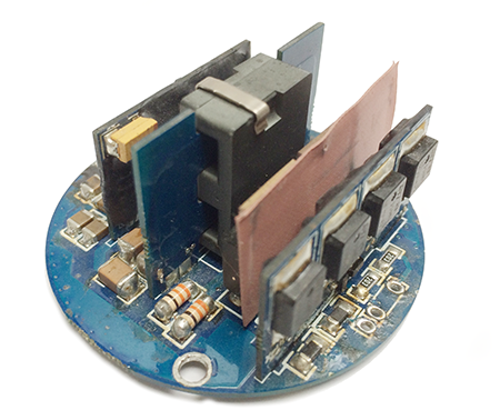
XV8C2 round HID ballast PCB
The XV8C2 is the improved and extended replacement for the XV8C. The XV8C2 is a round compact ballast PCB with a diameter of 53 mm. It is available as dual power models (DPM), 35 / 50 W and 50 / 70 W, and single power models (SPM). It drives D1S bulbs , and D2 type bulbs with an external ignitor or our XeSparQ™ D2/D1 igniter module.
The XV8C2 PCB is used in our round ballast designs, the XePod™ and XePuck™2. The ballast circuit board (PCB) is available for OEM only.
Key features:
- 30 / 50 W and 50 / 70 W dual power mode (DPM)
- Single power (SPM) of each power available on special request only
- 12 VDC or 24 VDC
- dimensions: Ø 58 mm, height 28 mm
- weight: 40 g (DPM and SPM) without wires
- ballast life expectancy:
> 3000 hours
DPM/SPM trigger wire:
- open contact: low W (35 on 35/50 model and 50 on 50/70 model)
- to ground: high W (high wattage setting)
- SPM: ON/OFF control
Parameters for DPM, SPM
XV8C2 35 W
XV8C2 50 W
XV8C2 70 W
Normal input voltage range (VDC
8.5-18.5 / 18-36
8.5-18.5 / 18-36
8.5-18.5 / 18-36
Input turn off (VDC)
< 5 / < 12
< 5 / < 12
< 5 / < 12
Turn on light output
>80% at 3 s
>80% at 3 s
>80% at 3 s
Steady state output power (W)
35 W ± 1 W
50 W ± 2 W
70 W ± 2 W
Maximum run-up output powern (W)
80
100
112
Max. steady state lamp current (A)
3.0 / 1.5
4.2 / 2.1
6.0 / 3.0
Max. inrush current @ 10.0 / 20.0 VDC (A)
8 / 4
10 / 5
12 / 6
Striking voltage
>1.3 kV
>1.3 kV
>1.3 kV
Reverse voltage protection (VDC)
up to 40
up to 40
up to 40
Startup & Open lamp circuit protection
latch off < 0.5 s
latch off < 0.5 s
latch off < 0.5 s
Ballast/lamp efficiency
92 %
92 %
92 %
Output steady state frequency (square wave)
500 +/- 50 Hz
500 +/- 50 Hz
500 +/- 50 Hz
Temperature range
-40 to +95 °C
-40 to +95 °C
-40 to +95 °C
EMI emissions and susceptibility
DO-160E
DO-160E
DO-160E
Weight (no wires/connectors, ±HS)
40 g
40 g
40 g
Thermal design requirement:
A mandatory cooling system provided by the customer must maintain a maximum operating temperature below 95ºC (203º F) on the hottest ballast PCB area. Tip: Cooler is always better.
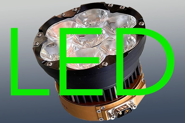
XePod™ round HID ballast
Key features:
- compact all-in one HID source with ballast/bulb
- digital XeStrike™ D-series XV8C ballast
- D1S bulb or our
- 35 or 50 watt
- DPM enabled (remotely switchable 30/50 watt
- 12 VDC or 24 VDC
- compact two part Al housing
- dimensions Ø 58 mm, length 55 mm
- weight is 272 gr
- water and dust proof, to IP67
DPM trigger wire:
open contact - 35 W (low wattage setting)
to ground - 50 W (high wattage setting)
SPM trigger wire: ON/OFF control
The XV8C is used in our round ballast design, the XePod.
The ballast circuit board (PCB) is available for OEM only. DPM trigger wire:
open contact - 35 W (low wattage setting)
to ground - 50 W (high wattage setting)

Parameter
XePod™ - 35 W
XePod™ - 50 W
Normal op. input voltage range
8-18 / 18-32 VDC
8-18 / 18-32 VDC
Start-up (turn-off voltage) , VDC
9.5 (6) / 18 (12)
9.5 (6) / 18 (12)
Starting input voltage range, VDC
7-16 / 14-32
7-16 / 14-32
Nominal output power
35W ± 2 W
50W ± 2 W
Maximum run up output power
70 W
100 W
Max. steady state lamp current
3.2 / 1.6 A
4.6 / 2.3 A
Max. inrush current at 13.5 / 27.0 VDC
6 / 3 A
8 / 4 A
Max. inrush current @ 10.0 / 20.0 VDC
8 / 4 A
10 / 5 A
Striking voltage
1.3 KV
1.3 KV
Steady state output volts (VAC)
60 to 110
60 to 110
Efficiency of D1S and ballast at nominal supply voltage
> 85 % / > 88 %
> 85 % / > 88 %
Triggered DPM in VDC
9 -18 / 18 - 36
9 -18 / 18 - 36
Output steady state frequency
500 +/- 20 Hz
500 +/-20 Hz
Temperature range
-40 to +105 °C
-40 to +105 °C
Temperature control (by custmer)
max. on case 70ºC
max. on PCB 70ºC
Weight (without bulb, heat sink)
272 g (9.5 oz)
272 g (9.5 oz)
Dimensions (without bulb, heat sink)
diameter: 58 mm
length: 55 mm
diameter: 58 mm
length: 55 mm
Thermal design requirement:
A mandatory cooling system provided by the customer has to maintain an ideal operating temperature of < 75º C (167º F), not to exceed 85ºC (185º F) on the ballast Al housing. Cooler is always better.
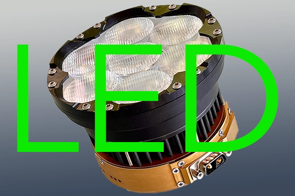
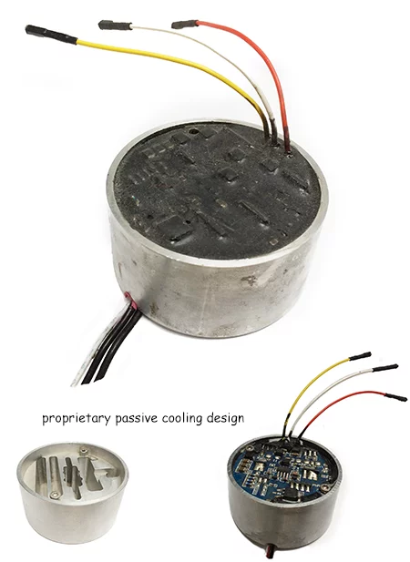
XePuck™2 round HID ballast
The XePuck™2 is the improved and extended replacement for the XePuck™.
The XePuck™2 is a round compact potted ballast in an Al case with a diameter of 53 mm. It is available as dual power models (DPM), 35 / 50 W and 50 / 70 W, and single power models (SPM). It drives D1S bulbs , and D2 type bulbs with an external ignitor or our XeSparQ™ D2/D1 igniter module.
Key features:
- Digital XeStrike™ D-series XV8C2 ballast PCB inside
- 30 / 50 W and 50 / 70 W dual power mode (DPM)
- Single power (SPM) of each power available on special request only
- 12 VDC or 24 VDC
- DPM enabled (remotely switchable 30/50 watt
- Proprietary passive cooling design
- Thermally conductive resin potted Al case
- Dimensions Ø 58 mm, height 31 mm
- Weight is 205 ± 10 g
- Water and dust proof, to IP67
DPM/SPM trigger wire:
- open contact: low W (35 on 35/50 model and 50 on 50/70 model)
- to ground: high W (high wattage setting)
- SPM: ON/OFF control
Parameters for DPM, SPM
XePuck™2 35 W
XePuck™2 50 W
XePuck™2 70 W
Normal input voltage range (VDC
8.5-18.5 / 18-36
8.5-18.5 / 18-36
8.5-18.5 / 18-36
Input turn off (VDC)
< 5 / < 12
< 5 / < 12
< 5 / < 12
Turn on light output
>80% at 3 s
>80% at 3 s
>80% at 3 s
Steady state output power (W)
35 W ± 1 W
50 W ± 2 W
70 W ± 2 W
Maximum run-up output powern (W)
80
100
112
Max. steady state lamp current (A)
3.0 / 1.5
4.2 / 2.1
6.0 / 3.0
Max. inrush current @ 10 / 20 VDC (A)
8 / 4
10 / 5
12 / 6
Striking voltage
>1.3 kV
>1.3 kV
>1.3 kV
Reverse voltage protection (VDC)
up to 40
up to 40
up to 40
Startup & Open lamp circuit protection
latch off < 0.5 s
latch off < 0.5 s
latch off < 0.5 s
Ballast/lamp efficiency
92 %
92 %
92 %
Steady state frequency, square wave
500 +/- 50 Hz
500 +/- 50 Hz
500 +/- 50 Hz
Temperature range
-40 to +95 °C
-40 to +95 °C
-40 to +95 °C
EMI emissions and susceptibility
DO-160E
DO-160E
DO-160E
Weight (no wires/connectors, ±HS)
200 ± 5 g
200 ± 5 g
200 ± 5 g
Thermal design requirement:
A mandatory cooling system provided by the customer must maintain a maximum operating temperature below 95ºC (203º F) on the hottest ballast PCB area. Tip: Cooler is always better.
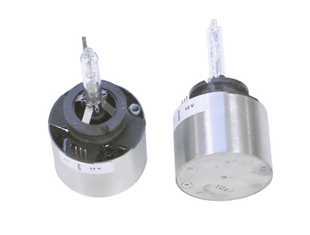
XePod™ mini round HID ballast
Key features::
- Our smallest D2D bulb type ballast - P32D socket
- digital XeStrike™ D-series ballast
- 35 or 50 W
- DPM enabled (remotely switchable 35/50 watt
- 12 VDC or 24 VDC
- power connection at the rear or front
- compact Al housing
- dimensions Ø 50 mm, length 36 mm
- weight is 140 gr
- water and dust proof, to IP67
DPM trigger wire:
open contact - 35 W (low wattage setting)
to ground - 50 W (high wattage setting)
SPM trigger wire: ON/OFF control
Parameter
XePod™ mini 35
XePod™ mini 50
Normal op. input voltage range
8-18 / 18-32 VDC
8-18 / 18-32 VDC
Start-up (turn-off voltage) , VDC
9.5 (6) / 18 (12)
9.5 (6) / 18 (12)
Starting input voltage range, VDC
7-16 / 14-32
7-16 / 14-32
Nominal output power
35W ± 2 W
50W ± 2 W
Maximum run up output power
70 W
100 W
Max. steady state lamp current
3.2 / 1.6 A
4.6 / 2.3 A
Max. inrush current at 13.5 / 27.0 VDC
6 / 3 A
>8 / 4 A
Max. inrush current @ 10.0 / 20.0 VDC
8 / 4 A
10 / 5 A
Striking voltage
1.3 KV
1.3 KV
Steady state output volts (VAC)
60 to 110
60 to 110
Efficiency of D1S and ballast at nominal supply voltage
> 90 % / > 90 %
>90 % / > 90 %
Triggered DPM in VDC
9 -18 / 18 - 36
9 -18 / 18 - 36
Output steady state frequency
500 +/- 50 Hz
500 +/-50 Hz
Temperature range
-40 to +95 °C
-40 to +95 °C
Temperature control (by custmer)
max. on case 70ºC
max. on PCB 70ºC
Weight (without bulb, heat sink)
140 g (4.9 oz)
140 g (4.9 oz)
Dimensions (without bulb, heat sink)
diameter: 50 mm
length: 36 mm
diameter: 50 mm
length: 36 mm
Thermal design requirement:
A mandatory cooling system provided by the customer has to maintain an ideal operating temperature of < 75º C (167º F), not to exceed 85ºC (185º F) on the ballast Al housing. Cooler is always better.
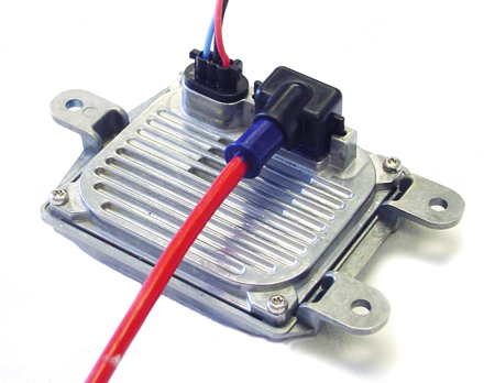
Teflon® cable description
Our proprietary double shielded cables are used for slected XeVision HID Xenon lighting systems. We produce the cables in custom length of 1, 2, 4, and 6 feet.
The shielded Teflon® cables are used between the ballast and the lamp and are pre-assembled with shielded connectors and are a major factor to suppress RMI/EMI.
On both ends there is a MQS connector which is shielded in contact with the ballast and the lamp, a major factor to suppress RMI/EMI.

click for larger image
The proprietary cable is double shielded including the connectors It is a Teflon® insulated cable with a Tinned copper braid shield and a Aluminum foil shield. The wires are Tinned copper strand with Teflon® insulation.
Electrical Characteristics:
Nom. Inductance .124 µH/ft Nom. Capacitance Conductor to Conductor @ 1 KHz 33 pF/ft Nom. Cap. Cond. to Other Cond. & Shield @ 1 KHz 60 pF/ft Nom. Conductor DC Resistance @ 20 Deg. C 5.8 Ohms/1000 ft Nominal Outer Shield DC Resistance @ 20 Deg. C 3.9 Ohms/1000 ft Max. Operating Voltage - UL 300 V RMS Max. Recommended Current 5.4 Amps per conductor @ 25°C.
Compliances:
NEC/(UL) Specification, CMP CEC/C(UL) Specification CMP EU CE Mark, EU RoHS Compliant, EU RoHS.
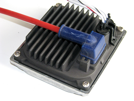
Silicone rubber cable description
The Silicone rubber double shielded cables are standard for all XeVision HID Xenon lighting systems. We produce the cables in custom length of 1, 2, 4, and 6 feet.
The cables are used between the ballast and the lamp and are pre-assembled with shielded connectors and are a major factor to suppress RMI/EMI.
On both ends there is a MQS connector which is shielded in contact with the ballast and the lamp, a major factor to suppress RMI/EMI.
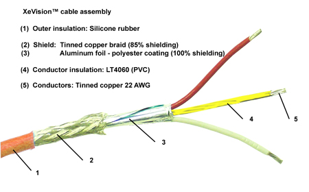
click for larger image
The cable is double shielded including the connectors It is a Silicone rubber insulated cable with a Tinned Copper braid shield and a Aluminum foil shield. The wires are Tinned copper strand with ORGALLOY® LE 6000 Polyamide 6 Alloy insulation to withstand high temperatures comparable to Teflon.